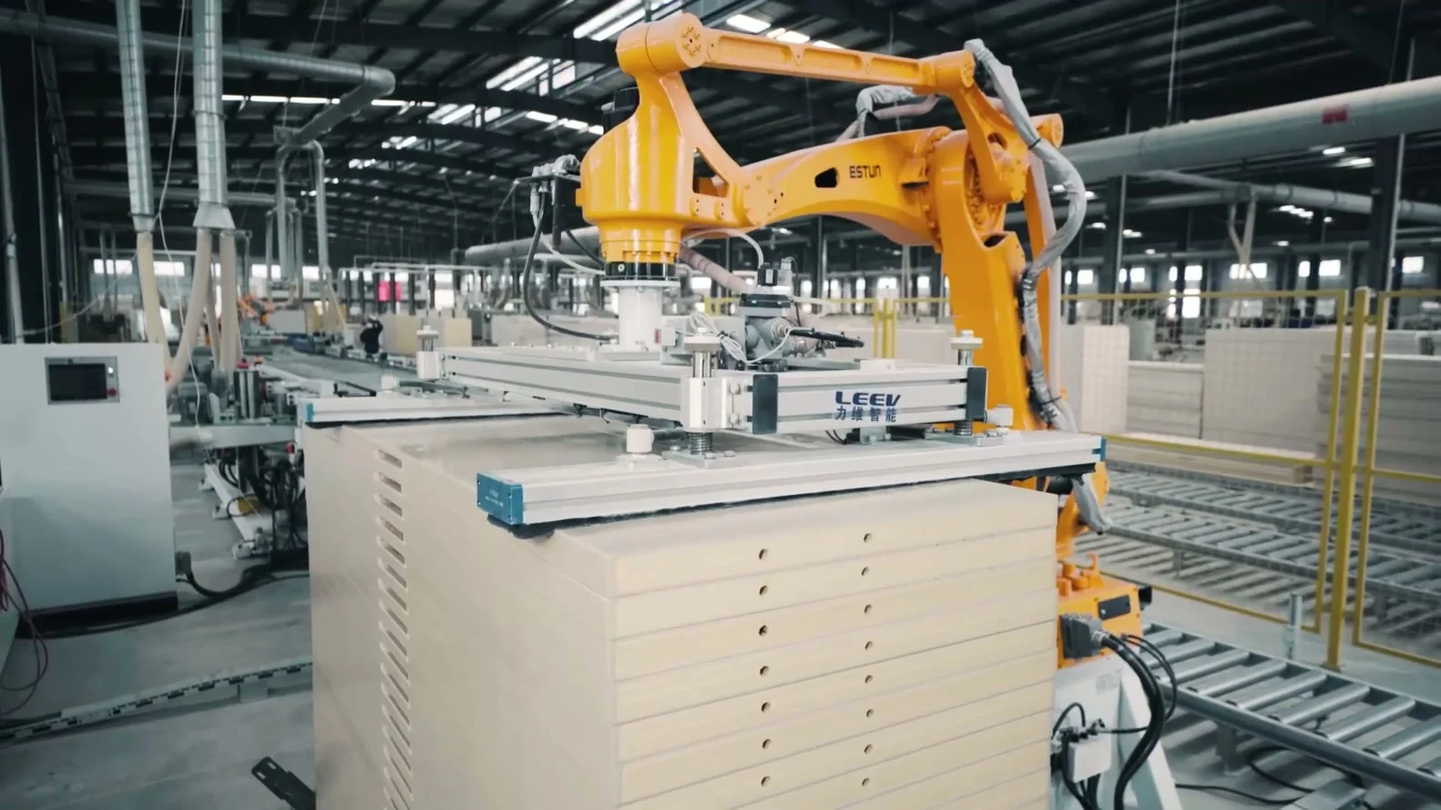
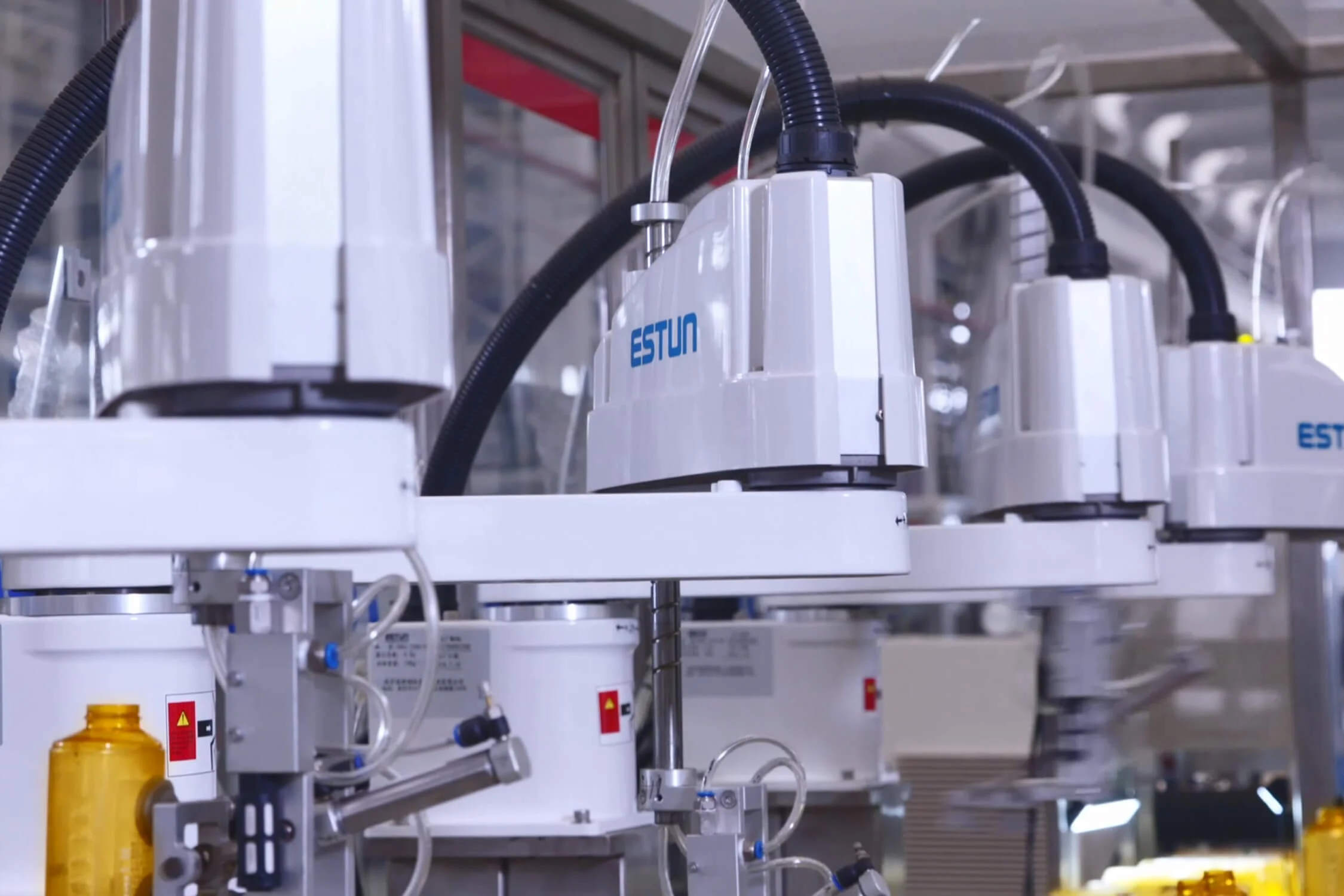
Components on a tray need orientation and placement into an assembly fixture. A camera may correct variable positions. This scenario combines vision, gripping and assembly checks without assuming their success.
Production requirements
Context to assess.
The requirement concerns an operation performed mainly in a plane, with a defined pickup orientation and height. Vanguard first checks whether an indexed tray is sufficient, then studies vision if positions vary. Representative components must include colour, reflectivity and presentation variation. The manufacturer photograph shows a SCARA installation; it does not demonstrate the camera or process described here.
Information to gather.
- Provide drawings, masses, tolerances and component samples. Specify visible faces, symmetry, fragile surfaces and orientation errors to reject.
- Describe trays, possible positions, height variation, ambient lighting and criteria distinguishing an acceptable part from an unknown one.
- Define the finished assembly, required checks, traceability information and expected behaviour when a part cannot be recognised or assembled.
Cell components.
Assess the ER6-600-SR-CE: maximum payload 6 kg, rated payload 2 kg and reach 600 mm. Tooling and the part must be included in load calculations.
Compare the ER10-800-SR-CE if geometry requires a different envelope. Selection must retain variant-specific data, including repeatability by axis.
Plan the camera, lens, lighting, gripper and assembly fixture. Specify the vision result format, coordinate frame and validation before transfer to the controller.
Operating sequence.
- Present the tray and identify the recipe. Acquire an image under the selected conditions, recognise the part and check the result against vision acceptance criteria.
- Transform the position into the calibrated robot frame, pick up the part and confirm retention. Reject out-of-range positions or ambiguous results.
- Place or assemble the part in the fixture, inspect the operation and record the relevant status. Provide a separate destination for unaccepted components.
Define acceptance.
- Test an identified sample set with agreed positions and surface conditions. Record recognised parts, correct rejections and misclassifications.
- Measure placement using the selected inspection method, then check image loss, poor lighting and missing grips. Also document recalibration.
References to assess.
These documented references support the initial selection. Payload with tooling, inertia, usable reach and options must be checked together.
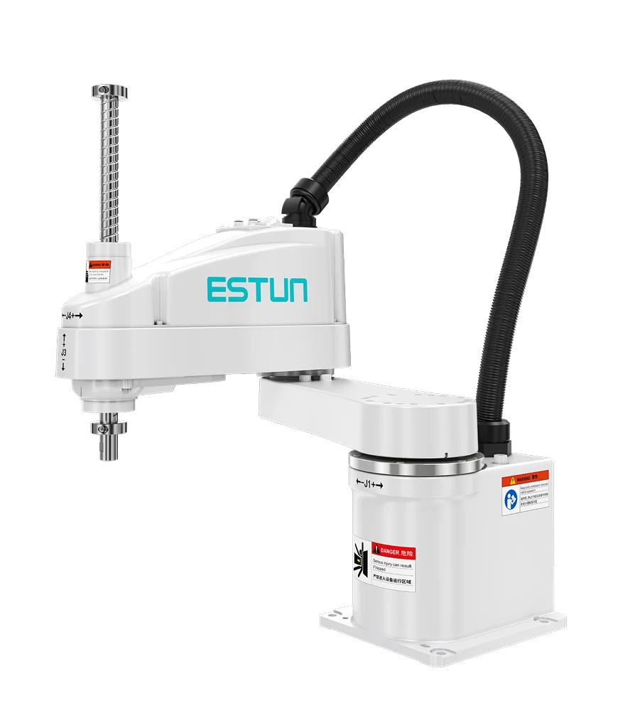 ESTUN ER6-600-SR-CE
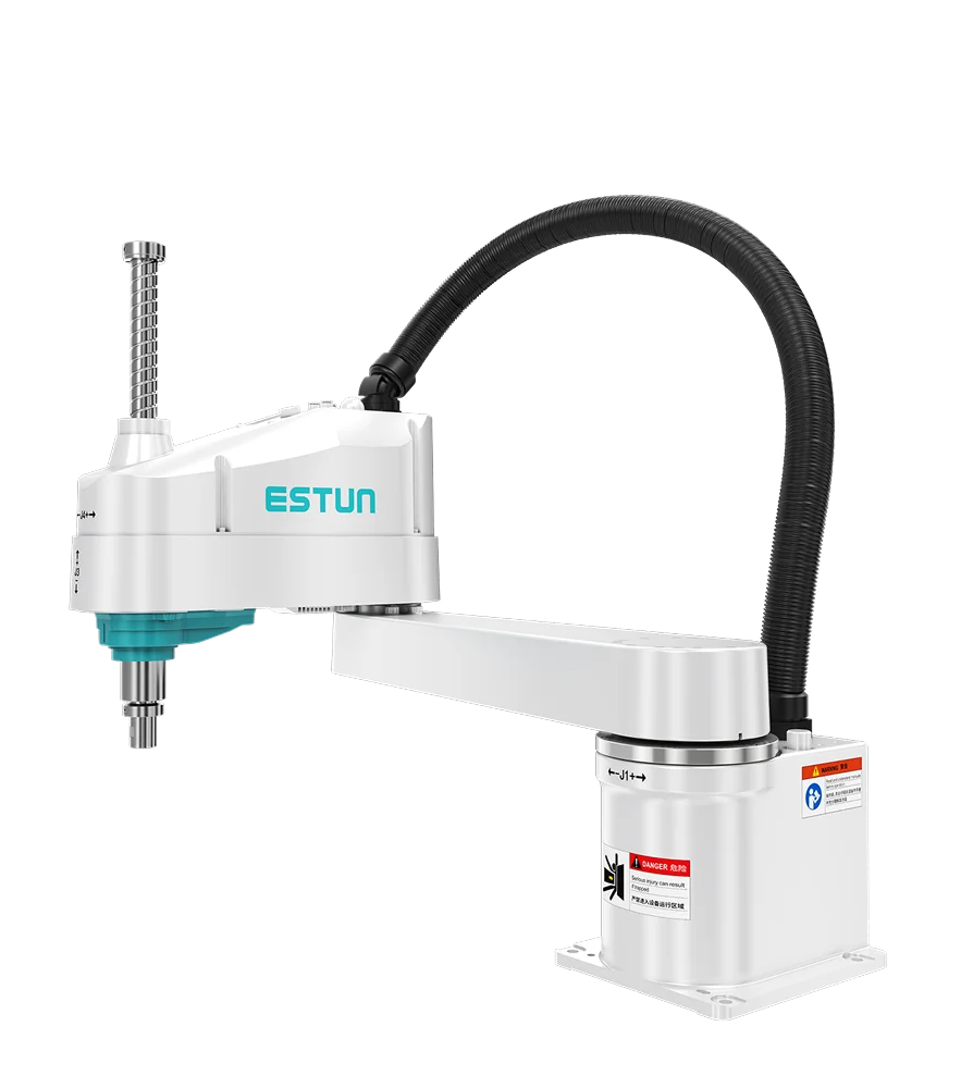 ESTUN ER10-800-SR-CE
Common questions
Points to clarify.
Does vision replace good positioning?
It may compensate for defined variation after trials. Simple mechanical presentation should still be compared before increasing cell complexity.
Can one program recognise every component?
References, variation and decision thresholds need definition. A new component requires samples and processing validation.